About the Product
Suibo ready to dive
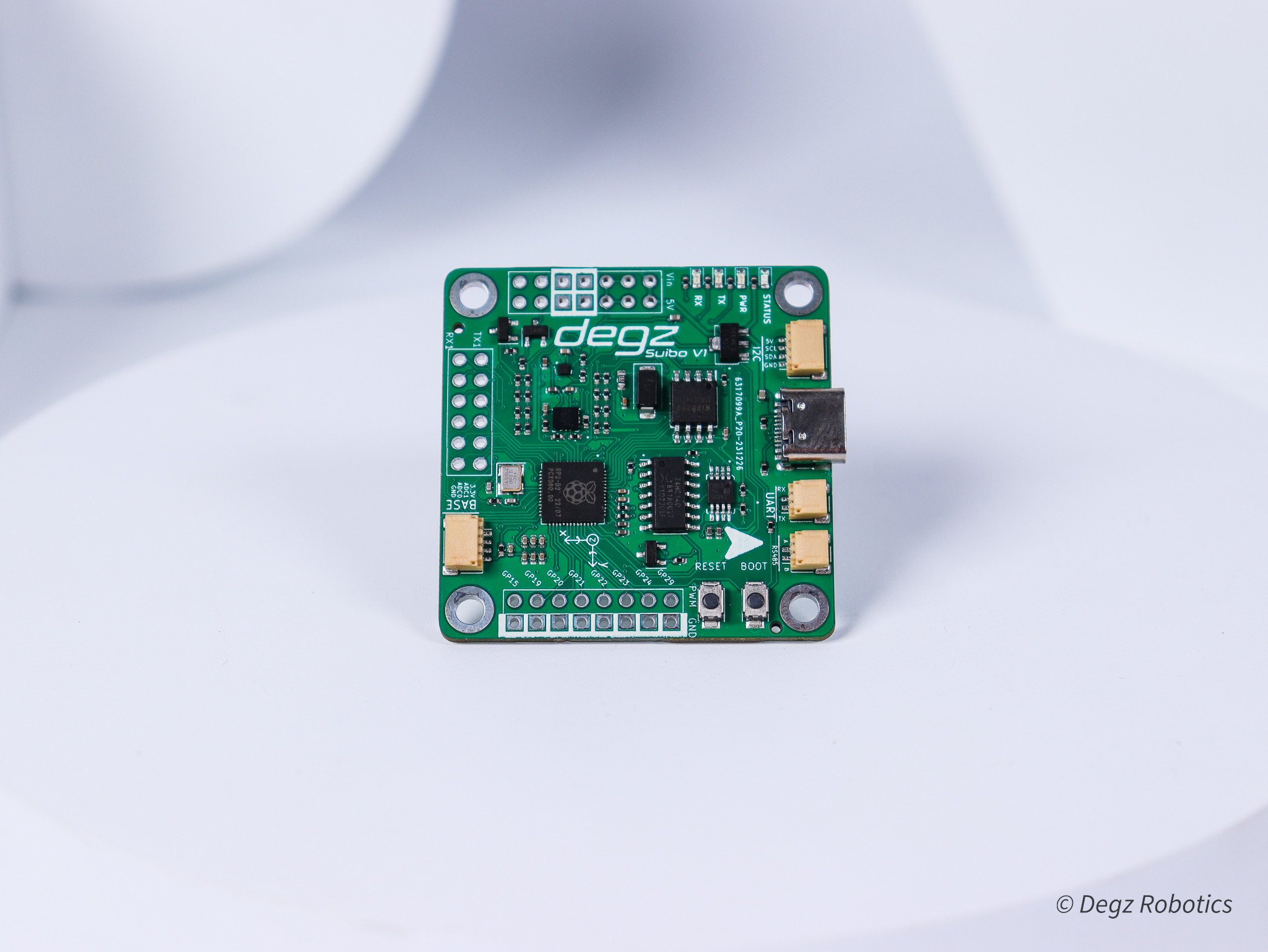
Suibo is an advanced control board designed for use in various robotics and automation projects. The board features 9-axis stabilization for autonomy and precision control needs and includes important sensors such as gyroscope, accelerometer and compass sensors. It can be used with a dual-core ARM M0 microcontroller, 8 MB external flash memory, IMU sensor and programmable LEDs. Furthermore, Suibo comes compatible with the Deep Diver ecosystem, which provides access to rich features such as the Dive Control Interface and the Python-based Dive Commander autopilot command library. Technically, it offers a flexible supply voltage between 3.3V and 6V and is compatible with various communication protocols (I2C, SPI, UART, RS485), making it suitable for many different projects, from unmanned underwater vehicles to rocket control systems. Suibo's design, adaptability and wide range of connections bring diversity and flexibility to your projects.
Product Technical Specifications
| Main Features | |
|---|---|
| Programming | Provides programming via USB. |
| Microcontroller | Uses a dual-core ARM M0 architecture microcontroller. |
| External Flash | Includes 8 Mb external flash memory. |
| Built-in Micro SD Card Slot | Built-in slot for micro SD card is available. |
| Electrical Characteristic | |
| Supply Voltage | Provides supply voltage between 3.3V - 6V. |
| Pin Voltage Value | A voltage value of 3.3V is used for the pins. |
| Environmental Units | |
| ADC | There is 1 Analog Digital Converter (ADC). |
| UART | 2 UART interfaces are available. |
| I2C | 2 I2C interfaces are available. |
| SPI | 2 SPI interfaces are available. |
| PWM | offers 18 PWM channels. |
| There are two buttons. One is the RESET button and the other is the BOOT button. | |
| Sensors | |
| IMU Sensor | has LSM6DS3 IMU sensor. |
| Compass | Uses a QMC6310 model compass sensor. |
| Programmable LED | Programmable LEDs are located on the board. |
| Physical | |
| Size | 45 x 45 mm |
| Connector | 2.54 mm Header |
| On JST Outputs | |
| I2C Compatible JST Connection | There is one I2C compatible JST on the board with 5V, SCL, SDA and GND ports. |
| UART Compatible JST Connection | There is one JST connection compatible with UART communication, including TX and RX pins. |
| RS485 Compatible JST Connection | One JST connection compatible for RS485 communication protocol is available on the board. |
| Base Board Compatible JST Connection | There is one JST connection compatible with the base board containing 3.3V, ADC0, ADC1 and GND. |
Pin diagram
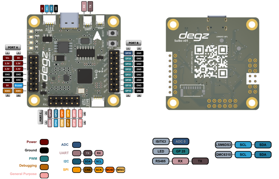
Pin Descriptions:
| Port A | Features |
|---|---|
| Vin (5V) | Used to supply 5V from an external power supply. |
| 3.3V | Provides 3.3V power output for systems on the board. |
| GND (Ground) | - |
| 5V | Provides a 5V power output. |
| Buzzer | Can be connected to a buzzer used for audio output. |
| SWD, SWC | SWC and SWD pins are used for serial wire debugging of the microcontroller. |
| Port B | Features |
| GP29 | is the ADC pin and is used to convert analog signals to digital data. |
| GP24, GP23, GP22, GP21, GP20, GP19, GP15 | are pins that can generate PWM signals and are used for tasks such as adjusting the brightness of LEDs or controlling motor speed. |
| Port C | Features |
| GP0 (TX) and GP1 (RX) are used for serial communication, TX is for sending data and RX is for receiving data. | |
| GP2 (SCL) and GP3 (SDA) | Used as clock (SCL) and data (SDA) line for I2C communication protocol. |
| GP6 (MISO), GP7 (MOSI), GP17 (CS), GP16 (SCK) | For SPI communication protocol, MISO is used to receive data from Master to Slave, MOSI is used to send data from Slave to Master, CS (Chip Select) is used to select the device to be activated and SCK (Serial Clock) is used to send clock signal. |
| GP10, GP11, GP12, GP13 | are general purpose pins and can be programmed for various input/output functions. |
You can reach us through the forum for questions and suggestions
📄️ Use of the product
Suibo – First Time Programming with Arduino IDE
📄️ Examples with Suibo
Suibo QMC6310 Magnetic Sensor Data Reading Code